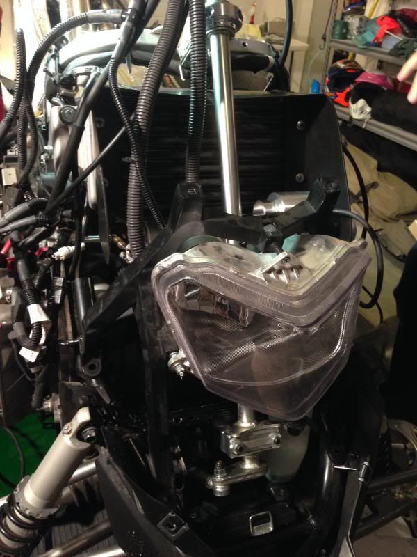
Reinstall Fuel Tank, Steering Column, Head Light & ETC
Step 86
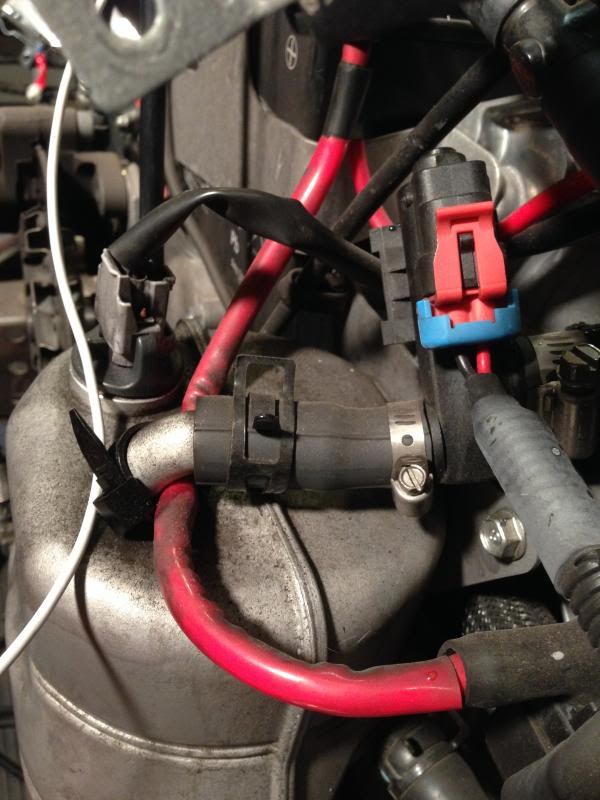
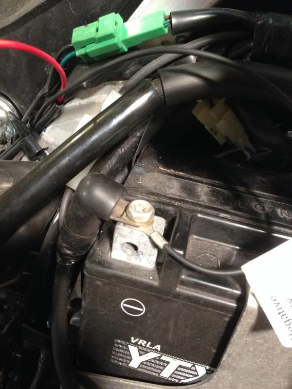
Connect the Battery Positive Cable back (Red cable, Hot)
Step 87
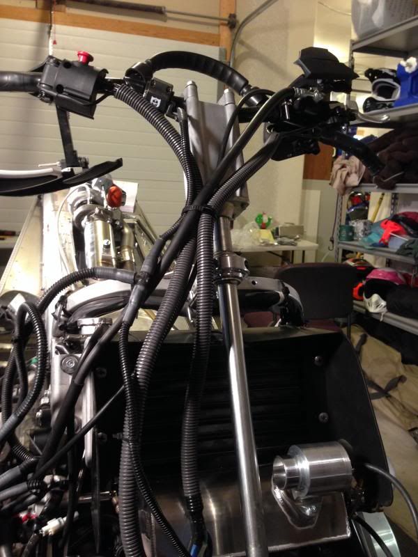
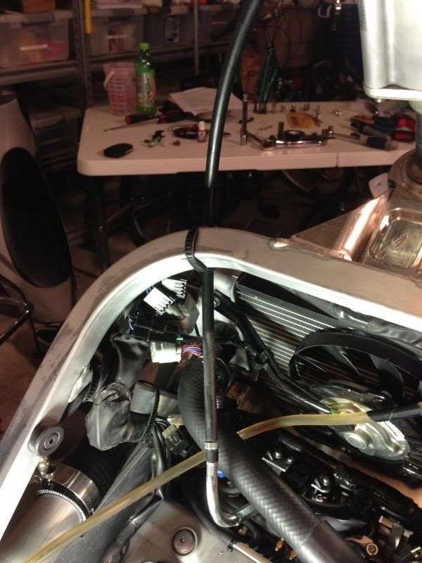
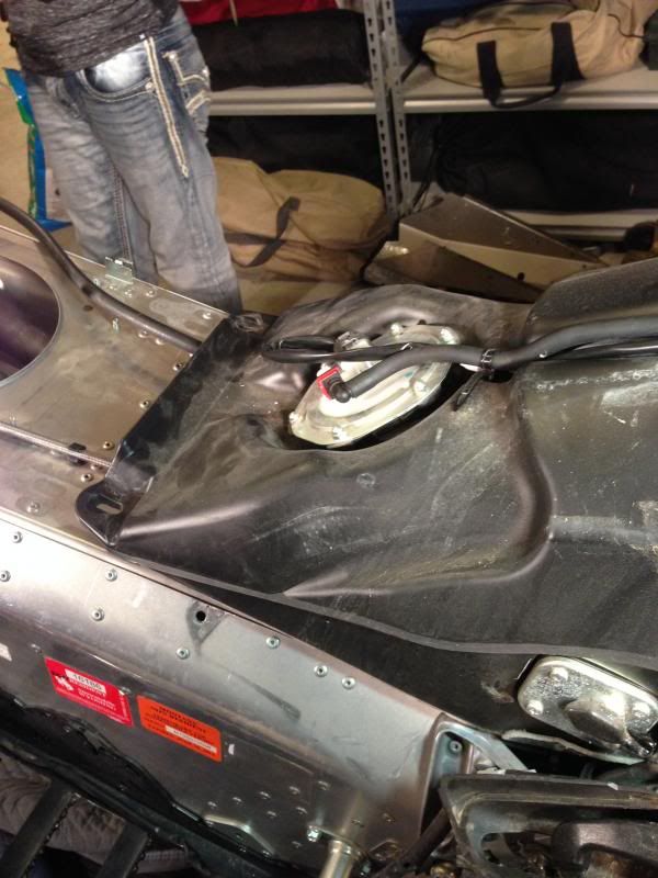
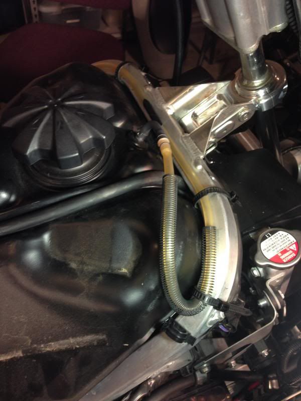
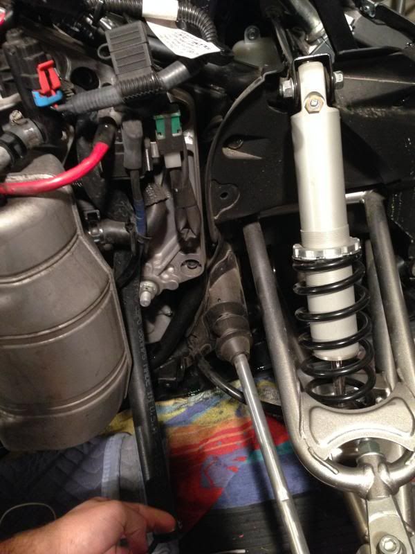
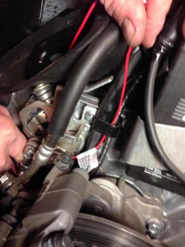
Route the Turbo oil return pump wiring from the pump down the RH side of the tunnel. Basically just use the tail light wiring as a guide.
Then the instructions say to follow the cables under the square aluminum OE hoop toward the battery.
Step 88
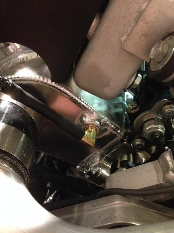
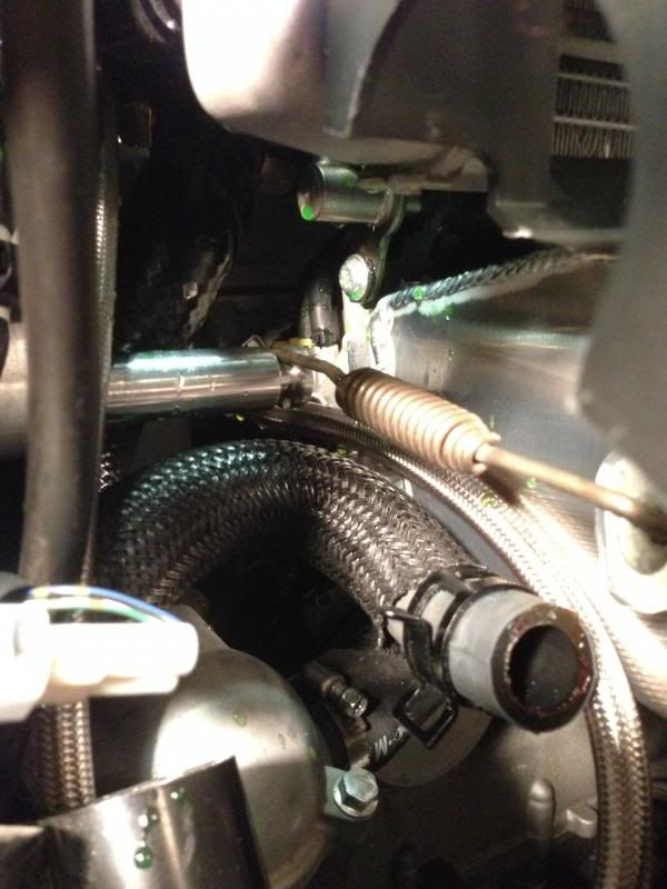
Connect the OE ground wire to the negative terminal including the ground lug for the new turbo oil pump harness
Step 89
This is the first time I had to ask someone to come over to my house and do something for me that i couldnt do. Remember this is still the first time I have ever attempted anything like this.
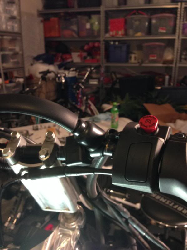
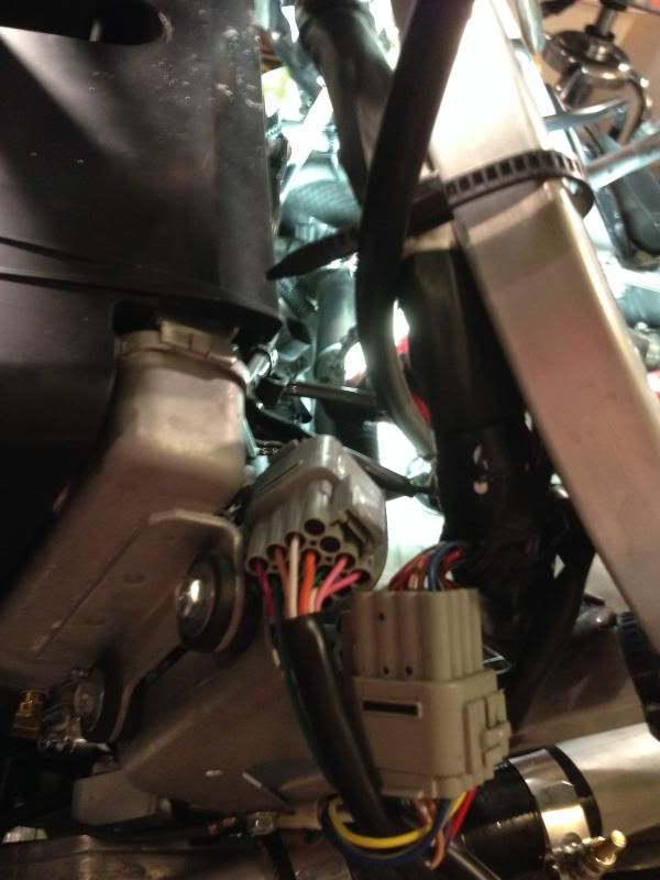
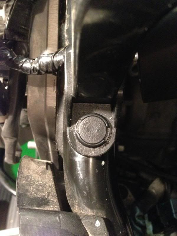
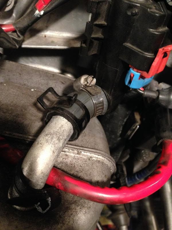
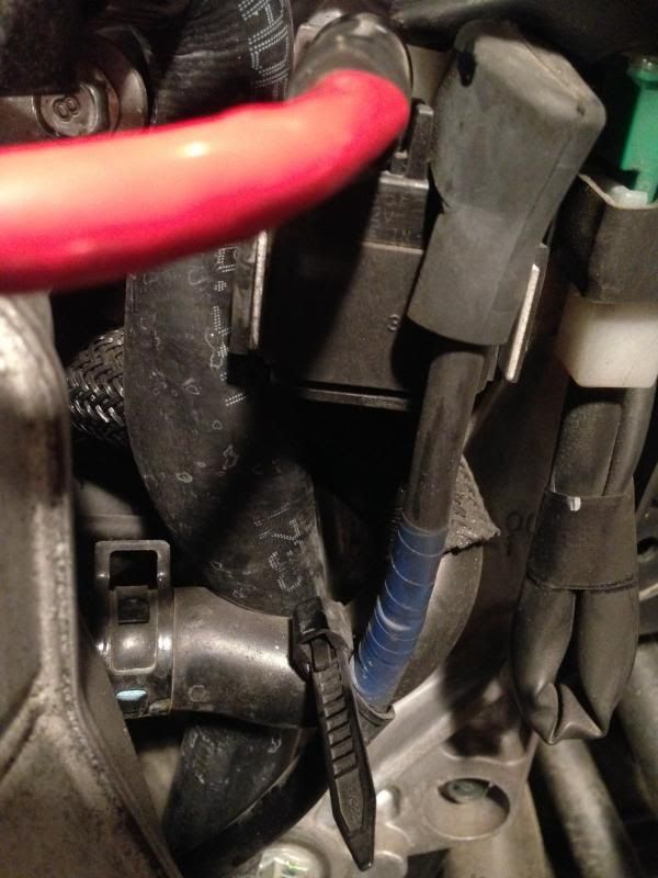
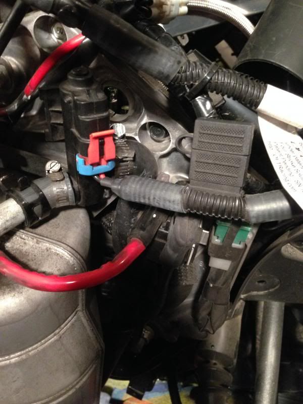
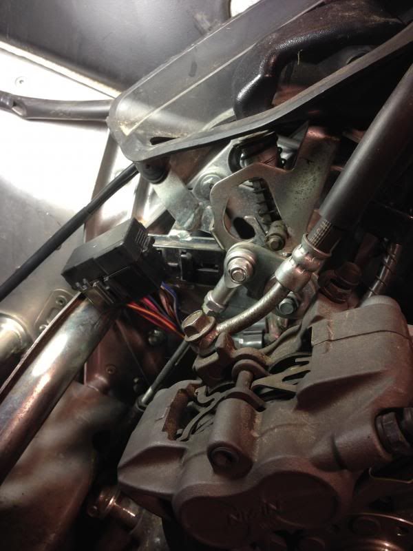
Step 89 requires that you solder the red cable from the new turbo oil pump to a specific Blue / White OE wire found coming out of the fuse box.
Now I wasnt able to find the fuse box for a bit since I had no idea where to look lol.
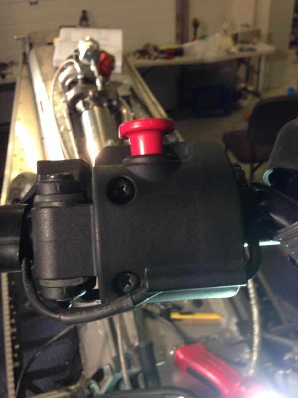
Its the black box and it is located just underneath and behind the handle used to engage the reverse.
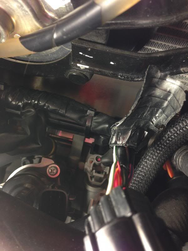
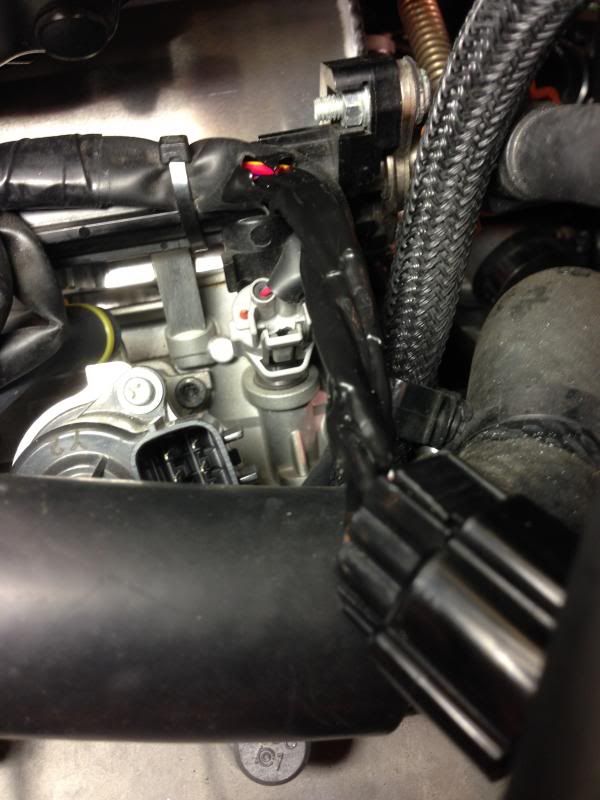
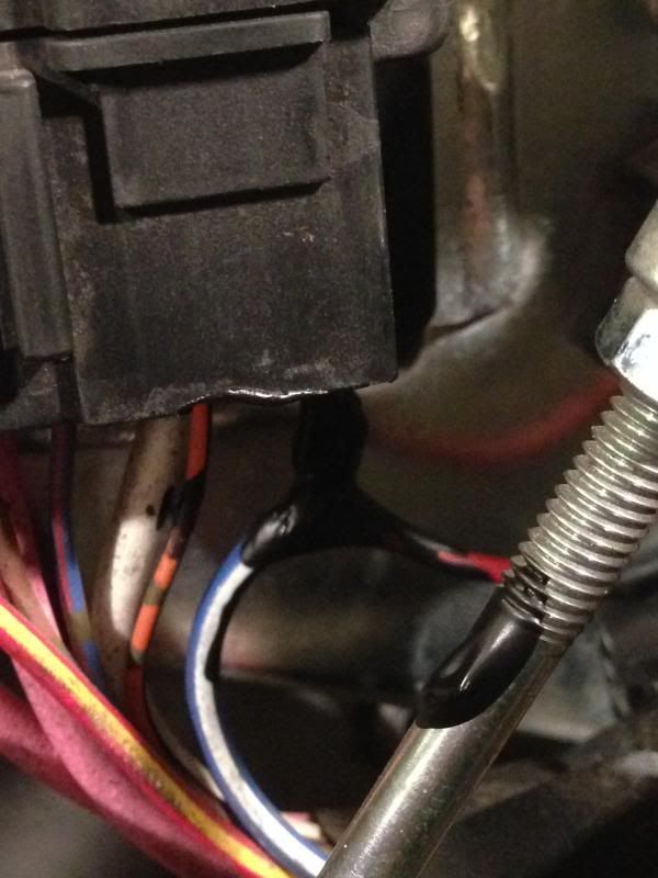
Once you locate the correct wire strip off about an inch of the insulation and solder the red wire to it.
My friend come over and he took about two inches more off the insulation of the red wire then was already done for you. Then braided it around the blue and white wire and then soldered it.
He did it so fast I apologize i didnt grab a picture. I was trying to learn how to do it and set my phone down long enough I didnt snap any pictures.
Essentially he just looped it around the blue/white wire and then twisted it tight and soldered it in place