Install the app
How to install the app on iOS

Follow along with the video below to see how to install our site as a web app on your home screen.

Note: This feature may not be available in some browsers.

  • Don't miss out on all the fun! Register on our forums to post and have added features! Membership levels include a FREE membership tier.

Full Lotus D7 Silber turbo build

Now it is time to install the intercooler. We moved the gas tank out of the way by removing the 2 tank bolts and simply lifting and sliding. Then we greased the O rings really well and slid the intercooler into place. We found by using a slight pry bar between the secondary drive shaft and the lower portion of the intercooler we could gain good leverage to seat the intercooler fully. Once the intercooler was seated fully the bolts lined up perfectly and we secured the intercooler in place.

Again because our sled is a 2007 the rear mounting bracket on the intercooler did not line up, so after a couple minutes of pondering we came up with this good solution. We removed all the bracket hardware including the rubber mount and in place installed a aircraft grade bolt with a sleeve and then a large washer along with a nylock nut. Then we took the rubber strap that was used to attach the upper portion of the stock airbox and fed it through a opening a lower bracket on by the intercooler. Then we simply pulled it over our bolt with washer and it held perfectly. This allows the intercooler to still have movement without being to loose. We also installed the coolant lines and the vacum lines.

Finally we installed the charge tube, we found it easiest to feed it from the turbo side and have the clamps removed from the charge tube to avoid hanging up on any lines. Once we got it through we did a couple slight adjustments on how far the silicon fittings were out and it fit perfect. The only thing we will have to do is change where the pull cord guide goes as it rubs on the charge tube, this procedure is outlined in the instructions.

Thanks

FLM Staff
www.holomis.com
info@holomis.com

IMG_0587.jpg IMG_0589.jpg IMG_0591.jpg IMG_0592.jpg IMG_0593.jpg IMG_0595.jpg IMG_0596.jpg
 
FLM and Justin,

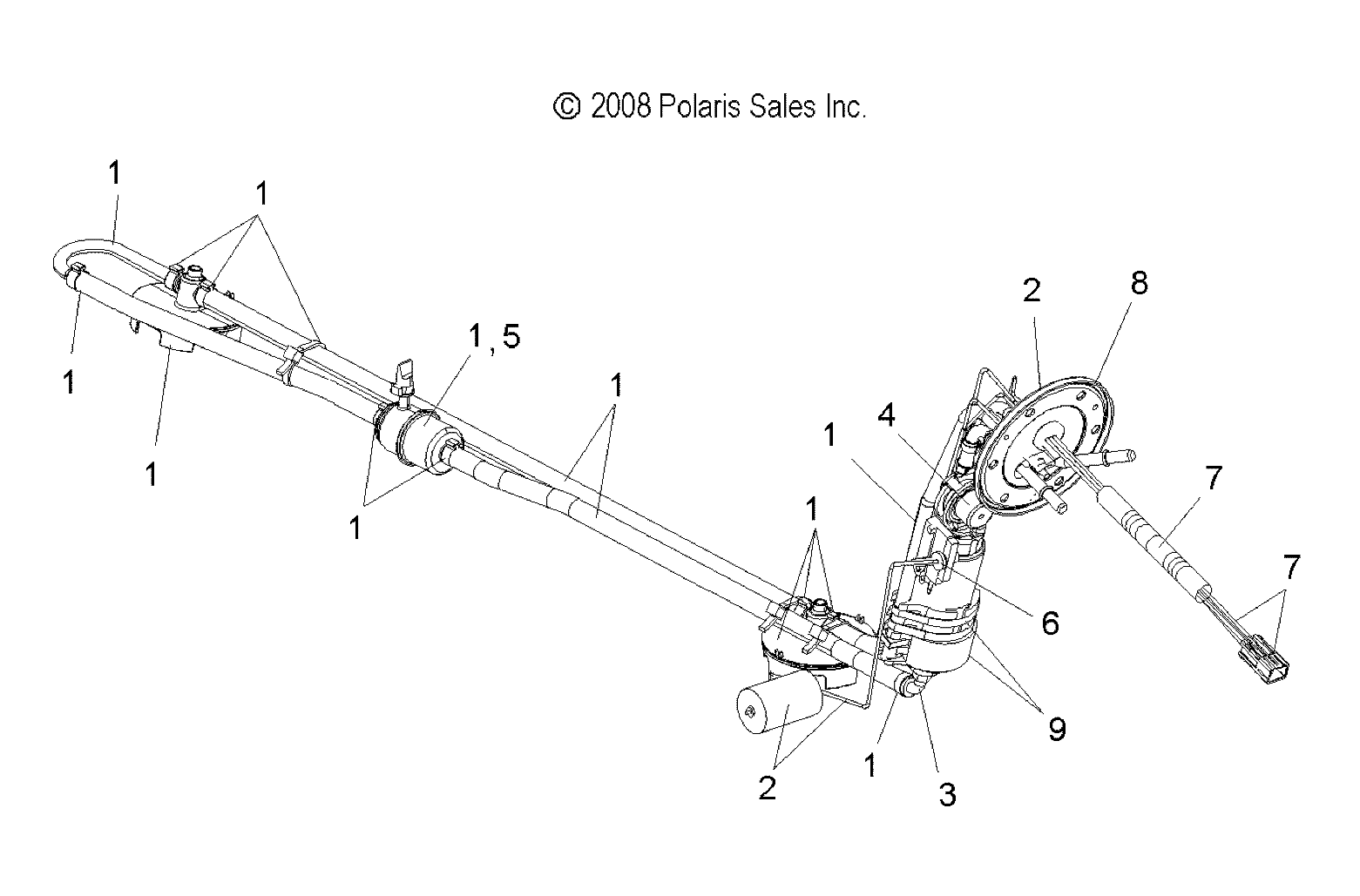
The photo you show has the FPR (fuel pressure regulator) simply removed... where is the block off plate that would allow the return fuel to circulate through the return lines in the tank, thru the fuel-vapor separator, into the Walbro fuel pickups and back into the pump... This is what helps to keep consistent feed into the fuel pump during operation... especially during low fuel level running.

Simply allowing the fuel to spill out of the FPR housing bypasses this very important fuel circuit.

You would be MUCH better served by removing the FPR housing altogether and putting a barb-union inline (in place of the FPR housing) on the 2007 sleds...allowing the return fuel to continue to circulate thru the lines for more consistent operation.

On the 2008+ with the FPR in the Walbro PFA (Pump flange assembly) this needs to be blocked of with a plate that allows the fuel to continue to circulate thru the "loop"

I hope you find this helpful.

attachment.php


SNOW%5CFUELPUMP%5CKITS.gif
 
Last edited:
FLM and Justin,

The photo you show has the FPR (fuel pressure regulator) simply removed... where is the block off plate that would allow the return fuel to circulate through the return lines in the tank, thru the fuel-vapor separator, into the Walbro fuel pickups and back into the pump... This is what helps to keep consistent feed into the fuel pump during operation... especially during low fuel level running.

Simply allowing the fuel to spill out of the FPR housing bypasses this very important fuel circuit.

You would be MUCH better served by removing the FPR housing altogether and putting a barb-union inline (in place of the FPR housing) on the 2007 sleds...allowing the return fuel to continue to circulate thru the lines for more consistent operation.

On the 2008+ with the FPR in the Walbro PFA (Pump flange assembly) this needs to be blocked of with a plate that allows the fuel to continue to circulate thru the "loop"

I hope you find this helpful.

attachment.php


SNOW%5CFUELPUMP%5CKITS.gif

The photo's were inserted out of sequence, we also just edited the post, because someone else sent a PM with the same statement. We did re-install the FPR without the small O ring. So essentially the FPR is now working as a block off plate. Hopefully this clears up any confusion!

Thanks

FLM Staff
www.holomis.com
info@holomis.com
 
Removing the lower o-ring WILL allow leakage around the lower end of the FPR... BUT..... I would still simply put in a barbed union and remove the FPR head...

The FPR still fits into the housing pretty closely... at low fuel demand (high injector bypass) thre is a lot of fuel passing by the FPR but this is still a restriction...Best to provide full flow here IMO.

All you have to do is remove the small oring and spacer ring and it still bypasses the fuel through the smart valves.

Its states it in the instructions.

Thanks
Justin
 
It's coming together nicely! When you wrapped your exhaust, did you wet down the heat wrap first? If you didn't do that, I would recommend doing it the next time around (i.e. if you decide to double weld the pipe seams). I've pulled my exhaust wrap twice off my sled and wetting the wrap down really makes it form fit the pipe when it dries.

Can't wait to see this sled on the snow.
 
All you have to do is remove the small oring and spacer ring and it still bypasses the fuel through the smart valves.

Its states it in the instructions.

Thanks
Justin

Hey Justin

On the 2007 D7's there is just a small O ring on the lower portion of the FPR, no spacer on the lower portion. So we just removed the small O ring. Should there be something else removed, or is it better to just go with a straight fitting there?

Thanks

FLM Staff
www.holomis.com
info@holomis.com
 
Removing the lower o-ring WILL allow leakage around the lower end of the FPR... BUT..... I would still simply put in a barbed union and remove the FPR head...

The FPR still fits into the housing pretty closely... at low fuel demand (high injector bypass) thre is a lot of fuel passing by the FPR but this is still a restriction...Best to provide full flow here IMO.

Hey Mountainhorse

I agree with you that a simple connector there will work well and we are going to end up doing that. I believe the reason just has the customer remove the spacer and O ring is because it works just fine (through his testing he knows this) but also for the simplicity of the it, then the customer doesn't have to remove the FPR housing, and put in the connector etc... As mentioned though we are going to install a connector just because I am a bit uncertain the 07 D7 is a bit different from the instructions.

Thanks

FLM Staff
www.holomis.com
info@holomis.com
 
It's coming together nicely! When you wrapped your exhaust, did you wet down the heat wrap first? If you didn't do that, I would recommend doing it the next time around (i.e. if you decide to double weld the pipe seams). I've pulled my exhaust wrap twice off my sled and wetting the wrap down really makes it form fit the pipe when it dries.

Can't wait to see this sled on the snow.

Hey Jonce

We haven't wrapped the pipe yet, so we will do the old water trick on it for sure.

Thanks

FLM Staff
www.holomis.com
info@holomis.com
 
Ok so we have made some more progress on the install. The first thing we did was go back to the stock FPR and remove it from the system, I don't think this is necesary but we were able to do it quite easily so we thought we would eliminate one thing from the system.

We simply removed the fuel pump system from the tank, then cut the metal band that held the stock FPR in place, then we cut the stock fuel line, then we removed one stock plastic strap so we could pick up some slack, and then attached the stock fuel line to the return line metal fitting, simple and quick worked great!

IMG_0601.jpg IMG_0602.jpg IMG_0603.jpg
 
We then moved onto the pull cord clearance step, following the supplied instructions we removed the support bar and cut off the cord guide moved it back 1.75" and re-welded it, fixed the clearance issue.

While we were in the cutting mood we trimmed the exhaust to the correct length as described in the instructions.

With this stage of the instructions finished it pretty much complete's our mechanical/fab portion of the installation, the rest of the process is basically running wires and cleaning tidying everything up.

I will say this, this kit has been very nice to install and as a manufacture we know the difficulties of producing a kit such as this to fit properly and Justin has acheived this and done a very nice job at it! You can tell there has been a tremendous amount of thought that has gone into this kit and it is a very complete kit with everything you need for the install right down to the plastic tie straps. Great job Justin.

IMG_0608.jpg IMG_0611.jpg IMG_0612.jpg IMG_0616.jpg IMG_0615.jpg IMG_0617.jpg
 
Ok now on to what we feel is the fun stuff (not quite riding yet) but still good stuff.

We have now started the clean up of the installation. First we started by securing the oil lines, using standoff's to ensure we will get no rub through on anything. You will see that we will standoff the majority of all of our lines in this install.

Also we have now installed the FPR, we looked at various locations to install this unit and decided on the recommended location. The only reason we looked at other options was because we wanted the gauge to be more readable, however after installing it in the recommended location we found that it was very readable and aslo easily adjustable. We also took into consideration that this unit once set is not touched again. We ensured that when we routed our lines there was nothing touching them and again stood them off from other lines and also each other. This method takes some extra time but we feel is worth it for trouble free operation and also makes the install look clean.

We will get some more updates down as we progress!

Thanks

FLM Staff
www.holomis.com
info@holomis.com

IMG_0618.jpg IMG_0619.jpg IMG_0620.jpg IMG_0621.jpg IMG_0622.jpg IMG_0623.jpg IMG_0624.jpg IMG_0625.jpg IMG_0626.jpg
 
Just ensure that the smart-valves lay/flop well like the original... they move around in the tank slightly which is what helps them to work consistently

Nice Photos and Write up!!


Ok so we have made some more progress on the install. The first thing we did was go back to the stock FPR and remove it from the system, I don't think this is necesary but we were able to do it quite easily so we thought we would eliminate one thing from the system.

We simply removed the fuel pump system from the tank, then cut the metal band that held the stock FPR in place, then we cut the stock fuel line, then we removed one stock plastic strap so we could pick up some slack, and then attached the stock fuel line to the return line metal fitting, simple and quick worked great!
 
Just ensure that the smart-valves lay/flop well like the original... they move around in the tank slightly which is what helps them to work consistently

Nice Photos and Write up!!

Yes that is one thing we made sure that the smart valves were not affected, this is why we had to remove the one factory tie strap to gain us some slack without effecting the length or position of the factory fuel system.

Thanks

FLM Staff
www.holomis.com
info@holomis.com
 
You were saying you are going to wrap your exhaust. Are you going to leave the aluminum heat shield on the pipe and just wrap over top of it? I have been thinking of doing the same but have not started yet. Post some pictures of what you do with the exhaust. Also I would like more pics and info of your front bumper. I have an 08 800 dragon, will that fit?

Here's another photo of the bumper, keep in mind this is the proto-type, so parts aren't CNC machined, there are gussets that still need to be added it is obviously not cleaned up etc... We don't like releasing photo's of the proto-types but we thought that we would give you a sneak peak of it in it's rough stage. We will be programing parts tomorrow for the final bumper now that we have determined exactly how it will be installed by the end customer.

Thanks

FLM Staff
www.holomis.com
info@holomis.com

IMG_0636.jpg
 
As far as the turbo install itself we did not get to much done today, only built our gauge pod. The kit does come with a gauge mount but we wanted to run EGT's as well as incorporate our Attitude tunning box into one system. So this is what we came up with. It needs to be cleaned up and sent to powder coat, but you get the idea.

Thanks

FLM Staff
www.holomis.com
info@holomis.com

IMG_0631.jpg IMG_0633.jpg IMG_0634.jpg
 
As far as the turbo install itself we did not get to much done today, only built our gauge pod. The kit does come with a gauge mount but we wanted to run EGT's as well as incorporate our Attitude tunning box into one system. So this is what we came up with. It needs to be cleaned up and sent to powder coat, but you get the idea.

Thanks

FLM Staff
www.holomis.com
info@holomis.com

I love that gauge pod!! How much would you charge for another one of those?
 
Premium Features


Back
Top