Install the app
How to install the app on iOS

Follow along with the video below to see how to install our site as a web app on your home screen.

Note: This feature may not be available in some browsers.

  • Don't miss out on all the fun! Register on our forums to post and have added features! Membership levels include a FREE membership tier.

DC Power on a PRO

Just tap into the red/white circuit... use that as the (+) trigger for YOUR relay... that will activate only when the sled is running above 700 rpm.

No need to cut/splice into the switch wires or harness.
 
Well... Silber and BD both tap from the red/white for the oil pump...
So their pump is only turned on when the chassis relay is triggered...

Your setup would activate the pump at the same time.

If you are worried about the pump loosing power... then put a led pilot light on the dash somewhere.

Ground... ground it to the chassis.
 
Ok mountainhorse, I am pretty convinced that running all my gauges, oil pump, injector, etc., off the DC PWR plug (with a 5A fuse inline) is a bad idea. Rectified AC is an issue for my sensors feeding my Vipec (floating ground, plus the voltage is not the most stable), so I think the best option is to put in a small battery and use the factory estart harness, then run everything off that via a relay?

A couple questions.
1. Is the battery charge circuit actually on a seperate coil from the rest? (this confuses me because when I power up the ECU via the ECU pwr plug, the fuel pump comes on too. Your previous posts put them on different circuits.)
2. Do I need to install a ground for the battery, or is it part of the factory harness?
3. Any suggestions on a really small battery?

Thanks in advance.
 
First, what sensors are feeding INTO your Vipec system?

1) Yes, on a separate circuit (see dwg below. When add external DC through the "ECM PWR" plug... you activate all red wire circuits... which includes the fuel pump.
The battery charge circuit is on the lighting coil regulator/relay a separate coil (Y). coming out of the lighting/charging regulator-rectifier is the red/dark-green wire... that is the battery charge wire.

2) Ground for the battery to the chassis..like with the factory battery plus ground to the ES sub harness.

3) battery... check the links in my post directly above.
http://www.ebay.com/itm/181000506327

At 4" x 2" x 2" and 18 oz... pretty small/light. (and cheap)

Also, Murph, SpeedCell batteries (used on factory Moto-GP bikes), on the fourm here here will be making plug/play harness with batteries soon.

A couple questions.
1. Is the battery charge circuit actually on a seperate coil from the rest? (this confuses me because when I power up the ECU via the ECU pwr plug, the fuel pump comes on too. Your previous posts put them on different circuits.)
2. Do I need to install a ground for the battery, or is it part of the factory harness?
3. Any suggestions on a really small battery?
attachment.php


attachment.php


.

STATORANDREGULATOR.png STATOR AND REGULATOR(S).png
 
Last edited:
Fuse block with trigger relay.

So i am doing what we spoke about battery to fuse block. Im looking to turn fuse block on and off with the key. I would like to use a spdt 12vdc relay to turn the power on and off.

Remember i do not have electric start just a battery with the harness. Will the key switch work better to provide a ground to the relay or power to the relay once engine is started. I believe it will provide ground and more precise sensor ground do you see any thing wrong with this?

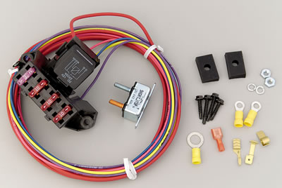
If you want a clean fuse block to use in your application... with the relay already mounted and assembled with wires... This one from Painless Wiring is pretty easy. Add a ground, power and trigger wires... then you have three output fuses for accessories.

The ES sub-harness has ground, red/white (for trigger), and DC 12volt to charge the battery...You can get them at a good price here http://www.summitracing.com/parts/prf-70113.


prf-70113_w.jpg


.
 
First, what sensors are feeding INTO your Vipec system?

1) Yes, on a separate circuit (see dwg below. When add external DC through the "ECM PWR" plug... you activate all red wire circuits... which includes the fuel pump.
The battery charge circuit is on the lighting coil regulator/relay a separate coil (Y). coming out of the lighting/charging regulator-rectifier is the red/dark-green wire... that is the battery charge wire.

2) Ground for the battery to the chassis..like with the factory battery plus ground to the ES sub harness.

3) battery... check the links in my post directly above.
http://www.ebay.com/itm/181000506327

At 4" x 2" x 2" and 18 oz... pretty small/light. (and cheap)

Also, Murph, SpeedCell batteries (used on factory Moto-GP bikes), on the fourm here here will be making plug/play harness with batteries soon.

attachment.php


attachment.php

.

So, correct me if I´m wrong here but if battery charge which is DC rectified runs on the same coil as the headlights, then I can add a battery connect it to the red/dg wire(battery charge) and run HIDs directly from the battery without risking anything!? Because its the same circuit only rectified and I wont change coil load!? (Removing headlights without added resistance usually is bad)
I dont know where I got it from but the batt.charge is 10amps right? With removed headlights and running them on the battery the capcity of the batt.charge would increase by the current draw of the stock lights? Or does the rectifier limit the amp output to the battery?
 
Last edited:
So, correct me if I´m wrong here but if battery charge which is DC rectified runs on the same coil as the headlights, then I can add a battery connect it to the red/dg wire(battery charge) and run HIDs directly from the battery without risking anything!?

You are correct. You connect the battery to the r/dg wire and back to the brown wire PLUS ground it to the chassis.
IMO.. Don't use the "cheepo" HID setups that cost around $70 ... the good ones will cost you $150 or so.
I like these.. that also have the bulb capping on them and very high quality ballasts... they have true 50w bulbs and 50w balasts. Order the optional bulb capping.
(CLICKY)


Because its the same circuit only rectified and I wont change coil load!?
(Removing headlights without added resistance usually is bad)
I don't understand your question.


I dont know where I got it from but the batt.charge is 10amps right?
The factory battery charge lead in the factory sub harness has a 10amp ciurcuit breaker on the r/dg wire... That is the factory set spec.

IMO, best to buy the factory harness and make a plug/play ES sub-harness so you are not cutting or tapping into the factory harness. Those are about $2
0

With removed headlights and running them on the battery the capcity of the batt.charge would increase by the current draw of the stock lights?

What are you trying to do here??

If you wanted to have more available DC Power.. you would need to run a higher capacity full-wave rectifier.

UNLESS you are running a Boondocker Turbo... Because they also rectify this AC voltage from the lighting coil when you run their intercooler... that also places an additional 4-6 amp load on this circuit ( 72watts)


Or does the rectifier limit the amp output to the battery?

Yep... up till the point that it goes bad.


...
 

Sled is all stock. I want HIDs in the headlights, peferably 55w. But, I also have a HID helmet light for my MX-bike with a 35 or 55w HID(switching depending on how many hours of light I need) powered by 1 or 2 5Ah Lipo packs(s).

2* 55w HIDs would work on the red/dg battery charge but not with a third HID on my helmet.
My thinking was with the stock headlights removed and running everything on the battery charge circuit I might have the amps for the stock headlights on top of that 10amps the red/dark green is capable of. I studied the wiring diagram but couldnt find a fuse @ 10amps. That breaker you mention, where is it and what type is it?
Maybe I´ll settle for 3*35w HIDs. That´ll keep the draw under 10amps.

Edit: I want the ballast for the helmetlight on the sled, getting rid of the battery and ballast in the backpack.
 
Which capacitor

What capacitor would you recommend. In the process of installing a fuse block that draws power off the red/green battery charge lead. I will run the silber oil pump, O2 gauge, & misc from the fuse block. Would like to install 1 capacitor inline to the fuse block that's suitable for the 10amp supply.

Thanks for all the great info.

Nice to read a topic from start to end with zero bitching & negitive BS.
 
TTT


What capacitor would you recommend. In the process of installing a fuse block that draws power off the red/green battery charge lead. I will run the silber oil pump, O2 gauge, & misc from the fuse block. Would like to install 1 capacitor inline to the fuse block that's suitable for the 10amp supply.

Thanks for all the great info.

Nice to read a topic from start to end with zero bitching & negitive BS.
 
Use a chassis capacitor from any CFI Polaris sled.

As a note... A capacitor is NOT a power supply like a battery... they work to provide stabilize the power supply. They will not power anything with the sled turned off.
This can be nice since you don't have worry about a battery being drained.

To tap into the system... best to buy the factory sub-harness for the Electric start equipped models detailed above.

Also, the red/dark-green wire will need to be grounded through headlight power ground.

.
 
Last edited:
Thanks for all of the info. & your contribution to this valuable thread!

See below in red:

Use a chassis capacitor from any CFI Polaris sled. P/N 4011114 ???

Also, the red/dark-green wire will need to be grounded through headlight power ground. Please clarify - I understand the red/dark green wire is to be used as the power supply but what do you mean by gounding through headlight power ground???.


Thanks again,


Glen
 
Well after a few weeks of checking this out we are making up a harness that plugs into the e start circuit under the right side cowl, it will be fused and available with or without a capacitor.
Primarily we did this to serve our lighting customers, but it looks like others could use a good source of strong DC power
Run up to 10 amps of Dc power safely with no fear of burning up electronics etc..
I should have these ready by the end of the week, if your interested let me know via PM
 
Merlin,

Capacitor
4011114 is the part... used all the way back to the 2005 900's.

You could also use an Accel battery-eliminator capacitor for the harleys...nice little unit. Accel #151308
www.ebay.com/itm/400346057804

For the ground... as far as I can tell, the brown wire to the

Also... looks like the 2013's have changed the wiring harness, capacitor, AC/DC regulator, stator, ECU amongst other items.

Until I can get my hands on my 2013 ... and a 2013 wiring diagram... all the above may not apply.


The good news is that the Electric start sub-harness (battery side) is the same for 2011-2013
 
Last edited:
......

Also... looks like the 2013's have changed the wiring harness, capacitor, AC/DC regulator, stator, ECU amongst other items.

Until I can get my hands on my 2013 ... and a 2013 wiring diagram... all the above may not apply.
....

So what does this mean for us 2013 guys? I would assume it is very similar.
 
Nubulin,

I'm not assuming anything at this point.

I have yet to get my hands on it.

Looks like the 2013 has an all new 32bit ECU and only one voltage regulator.

I don't yet know the setup.

BUT, since the ES harness is the same, if you get a new subharness from Cyclops or a factory harness... and run a battery, you should be OK.

I still only recommend running a 2amp fuse MAX in the holder as the factory recommends.

Probably more to come soon... but for now... I dont have the info needed to be accurate with information on the 2013's

Good info. I appreciate all the help on this power issue. Please post when you see the 13 wiring diagram. I am still trying to decide what to do on mine. When I do, I will post what I did. ES harness is ordered.

Thanks.
 
Premium Features


Back
Top