Install the app
How to install the app on iOS
Follow along with the video below to see how to install our site as a web app on your home screen.
Note: This feature may not be available in some browsers.
You are using an out of date browser. It may not display this or other websites correctly.
You should upgrade or use an alternative browser.
You should upgrade or use an alternative browser.
Supercharger build cont.
- Thread starter tundramonkey
- Start date
Link to part 1 of the build: http://www.snowest.com/forum/showthread.php?t=377496
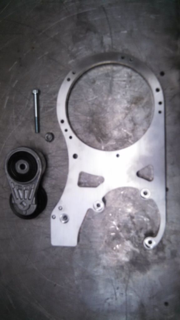
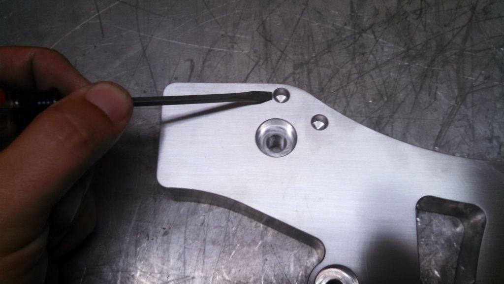
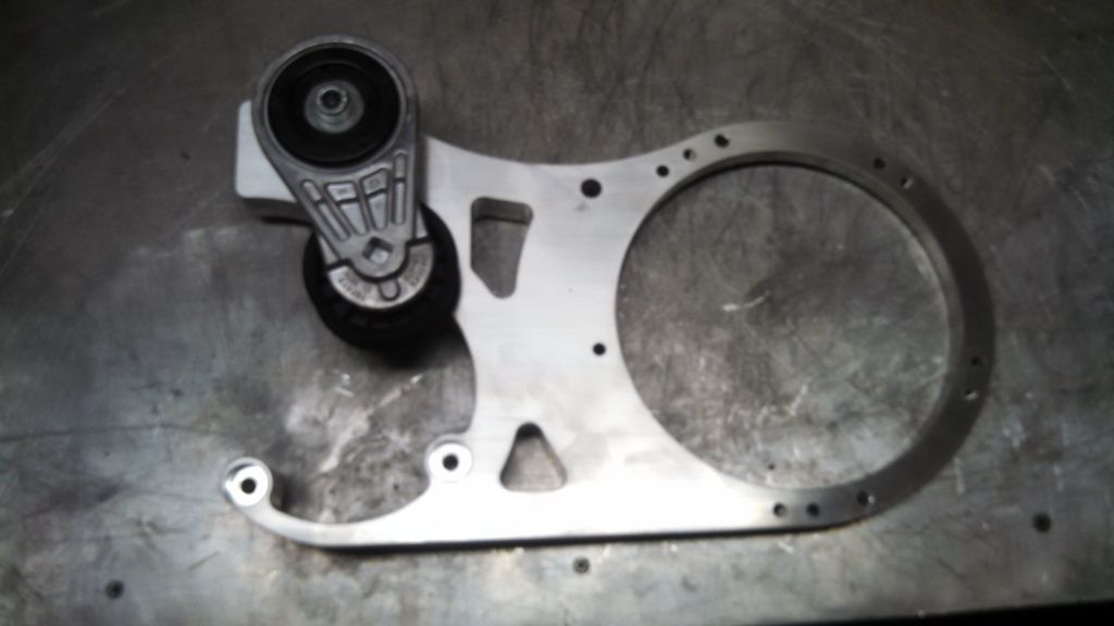
Case retaining ring and bracket spacer.
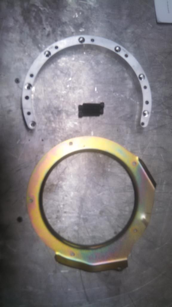
Installed on MAG side.
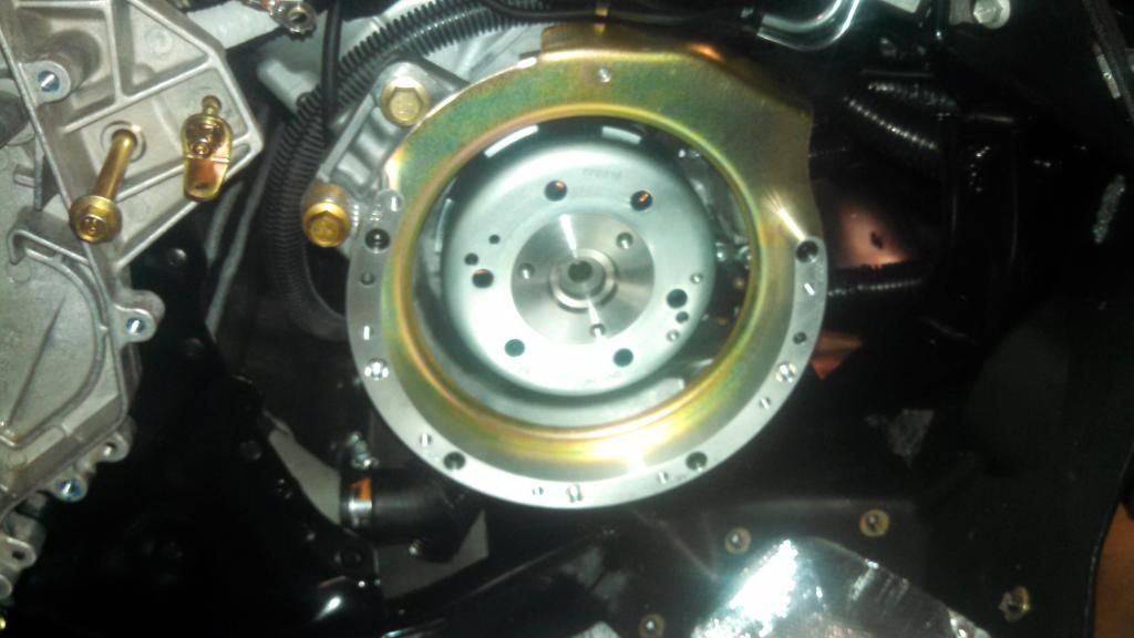
Case retaining ring and bracket spacer.

Installed on MAG side.

Last edited:
Replacement chassis support bar with spacer and bolts.
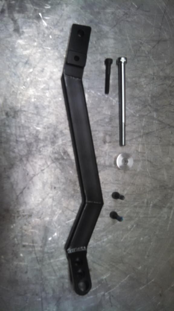
The new bar is relocated to the outside in the rear and moved to the rear upper A-arm mounting location in the front.
Longer bolts are provided for the front mounting location and the farthest rear location.
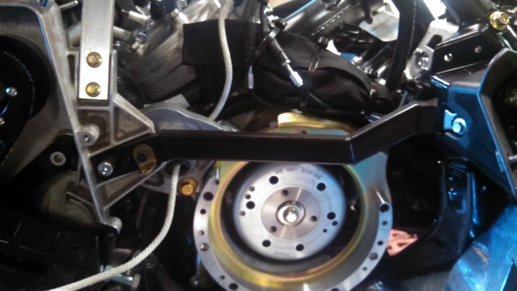
Spacer placed in old bracket location and ground relocated.
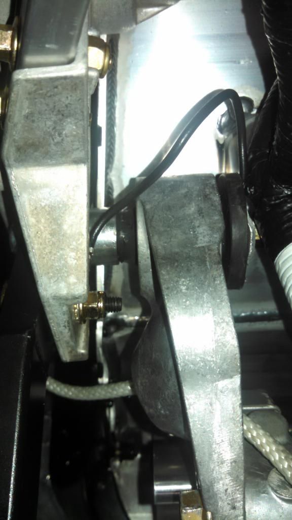
This is not provided with the kit, but I placed a piece of tubing over the threads of the back motor mount bolt.
I did this to prevent the threads from rubbing on the wiring harness that I relocated there.
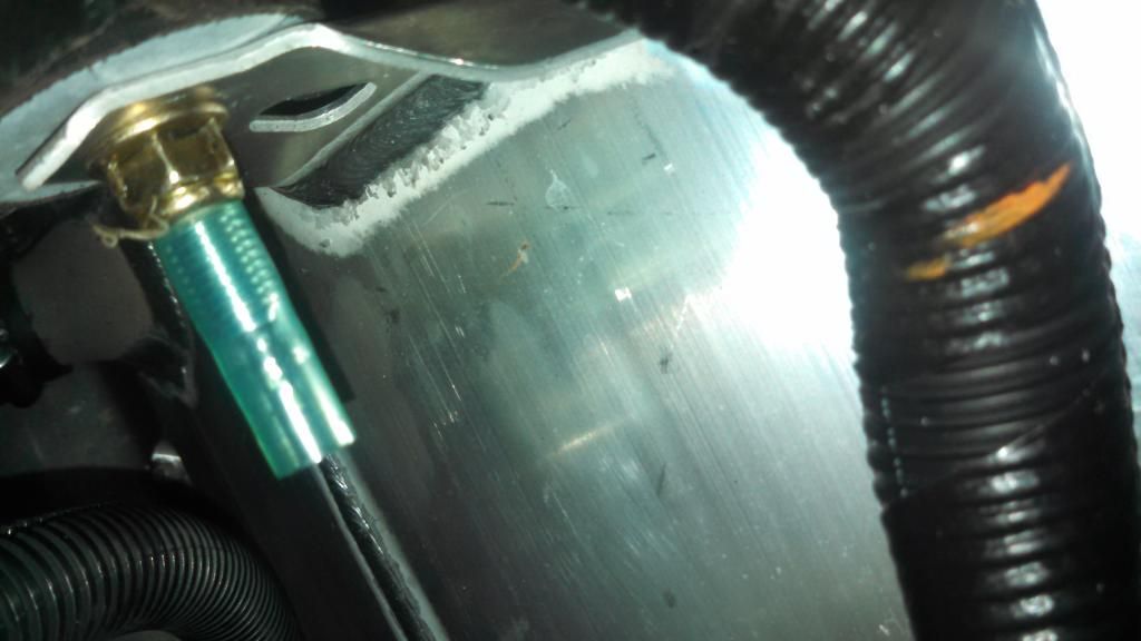
Relocated wiring harness.
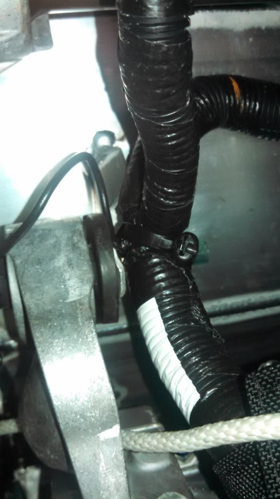

The new bar is relocated to the outside in the rear and moved to the rear upper A-arm mounting location in the front.
Longer bolts are provided for the front mounting location and the farthest rear location.

Spacer placed in old bracket location and ground relocated.

This is not provided with the kit, but I placed a piece of tubing over the threads of the back motor mount bolt.
I did this to prevent the threads from rubbing on the wiring harness that I relocated there.

Relocated wiring harness.

Last edited:
Mounting the Supercharger bracket is pretty straight forward except for two bolts.
As you can see in the picture the upper motor mount bolt hits the new chassis bracket.
I order to get this bolt in you need to remove the farthest rear bolt on the new chassis bracket.
This will allow you to lift on the PTO side of the motor so you have clearance to get the bolt past the new chassis support bar.
This also need to be done with the bolt in the 12 O'clock position.
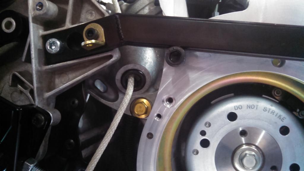
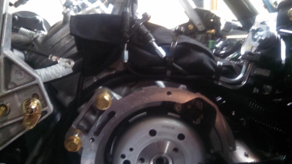
Lower pulley, belt and recoil hub mounted.
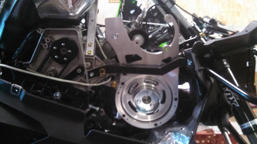
Recoil mounted.
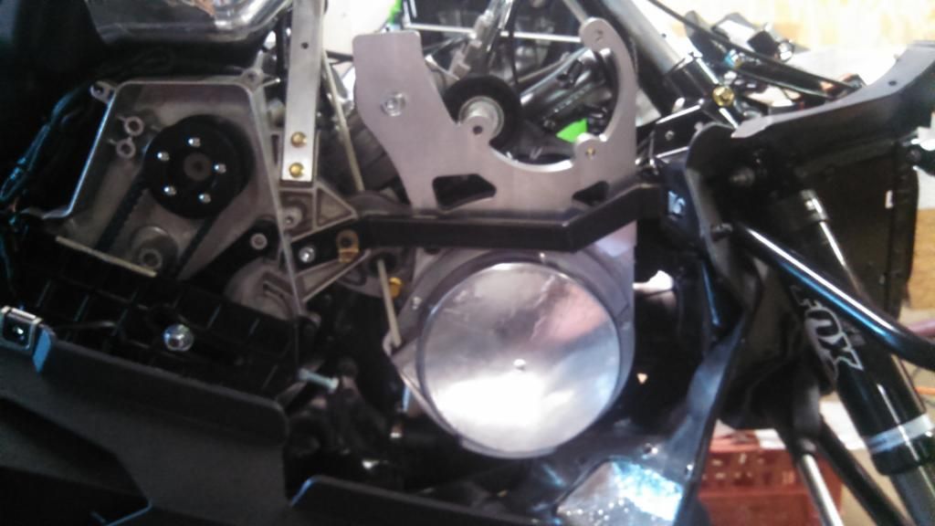
Spacer that is placed between the Supercharger bracket and case retaining ring in the 12 O'clock position.
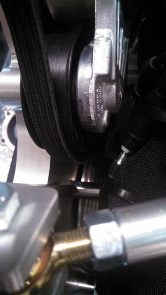
As you can see in the picture the upper motor mount bolt hits the new chassis bracket.
I order to get this bolt in you need to remove the farthest rear bolt on the new chassis bracket.
This will allow you to lift on the PTO side of the motor so you have clearance to get the bolt past the new chassis support bar.
This also need to be done with the bolt in the 12 O'clock position.

Lower pulley, belt and recoil hub mounted.

Recoil mounted.

Spacer that is placed between the Supercharger bracket and case retaining ring in the 12 O'clock position.

Last edited:
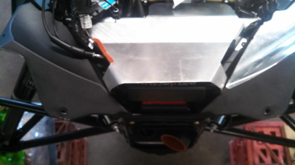
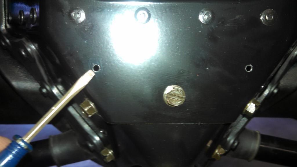
The suggested place to put the Power Commander V fuel controller is under the ECU.
The are two (2) existing holes in the front nose piece. I decided to drill two (2) more towards the
front of the nose piece so I could use tie wraps to securely mount the PCV.
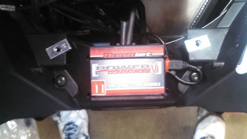
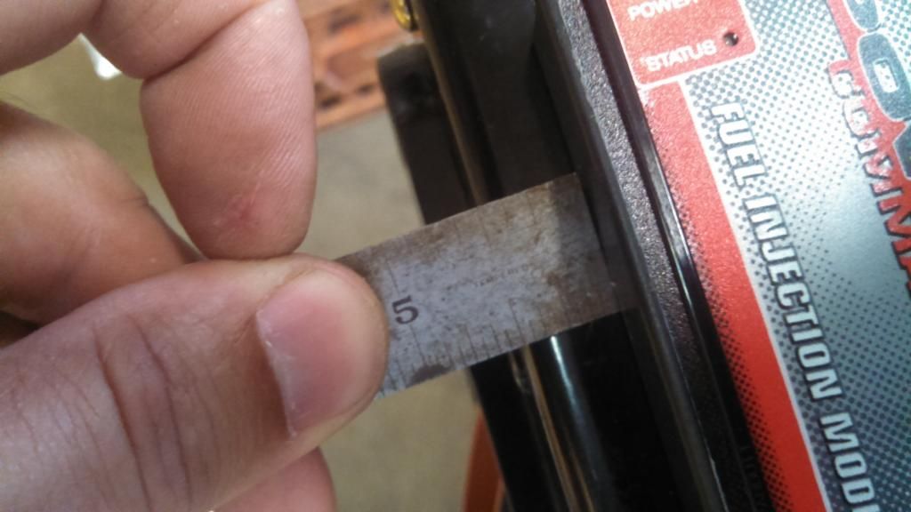
When you place the PCV fuel box you need to make sure you mount is approximately 1/2 inch back from the front.
If not the front plastic nose piece will not fit due to part of the piece that rests on top of the nose piece.
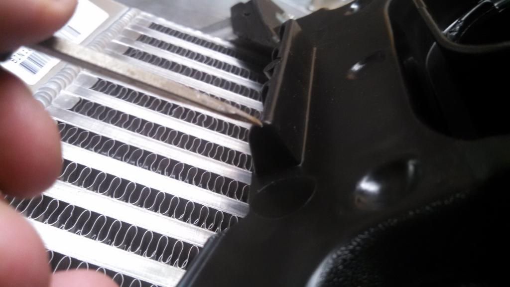
If you look directly in the middle of this picture you can see how that part of the plastic nose sits on top of the nose piece just in front of the PCV.
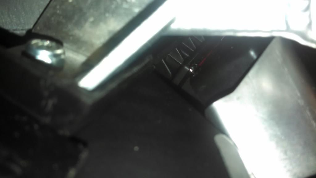
Another thing I did was to place a small amount of RTV around the mini USB plug that plugs into the side of the PCV.
You can see it in the first picture of this post. I routed the USB wire out the side from under the side of the metal heat
shield that sit over the ECU and follow the throttle cable up the support post. The end is fed down the steering post to
allow easy access for fuel adjustments.

Here's a picture with everything mounted in place.
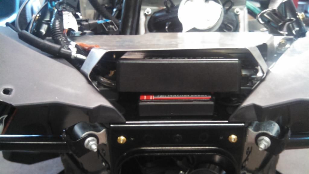
I didn't like the way the wires coming out from under the heat shield hit the sharp edge, so I
split a small fuel line and placed it along that edge with some RTV.
The are two (2) existing holes in the front nose piece. I decided to drill two (2) more towards the
front of the nose piece so I could use tie wraps to securely mount the PCV.

When you place the PCV fuel box you need to make sure you mount is approximately 1/2 inch back from the front.
If not the front plastic nose piece will not fit due to part of the piece that rests on top of the nose piece.


If you look directly in the middle of this picture you can see how that part of the plastic nose sits on top of the nose piece just in front of the PCV.

Another thing I did was to place a small amount of RTV around the mini USB plug that plugs into the side of the PCV.
You can see it in the first picture of this post. I routed the USB wire out the side from under the side of the metal heat
shield that sit over the ECU and follow the throttle cable up the support post. The end is fed down the steering post to
allow easy access for fuel adjustments.

Here's a picture with everything mounted in place.

I didn't like the way the wires coming out from under the heat shield hit the sharp edge, so I
split a small fuel line and placed it along that edge with some RTV.

Last edited:
Here's is the fan the mounts on the back of the intercooler.
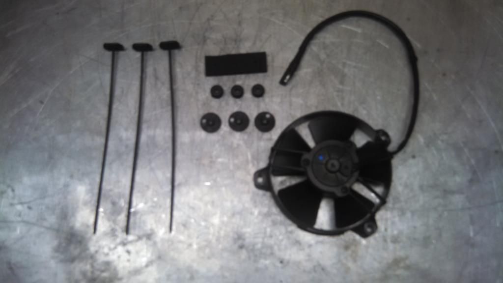
I recommend that you place the plastic nose piece with the intercooler mounted on it on the front of the sled.
This allows you to place the fan under and mark it location to ensure it will not hit anything.
Once this is done, place one of the provided rubber grommets over the plastic piece that secures the fan to the intercooler.
Slide the plastic piece through the intercooler, then place the provided foam piece over and secure in place.
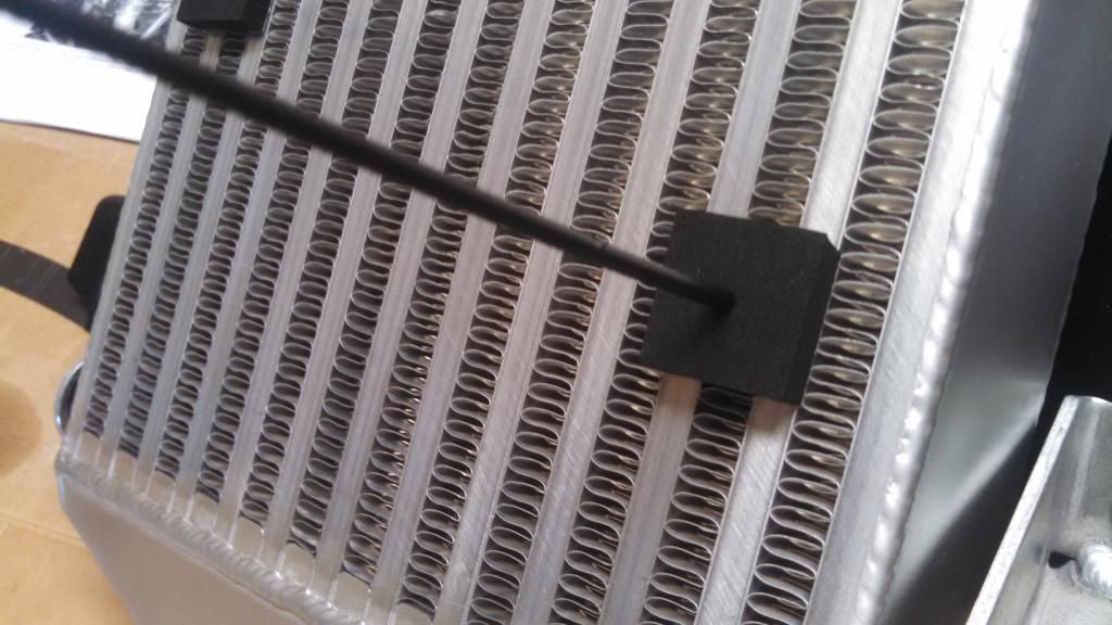
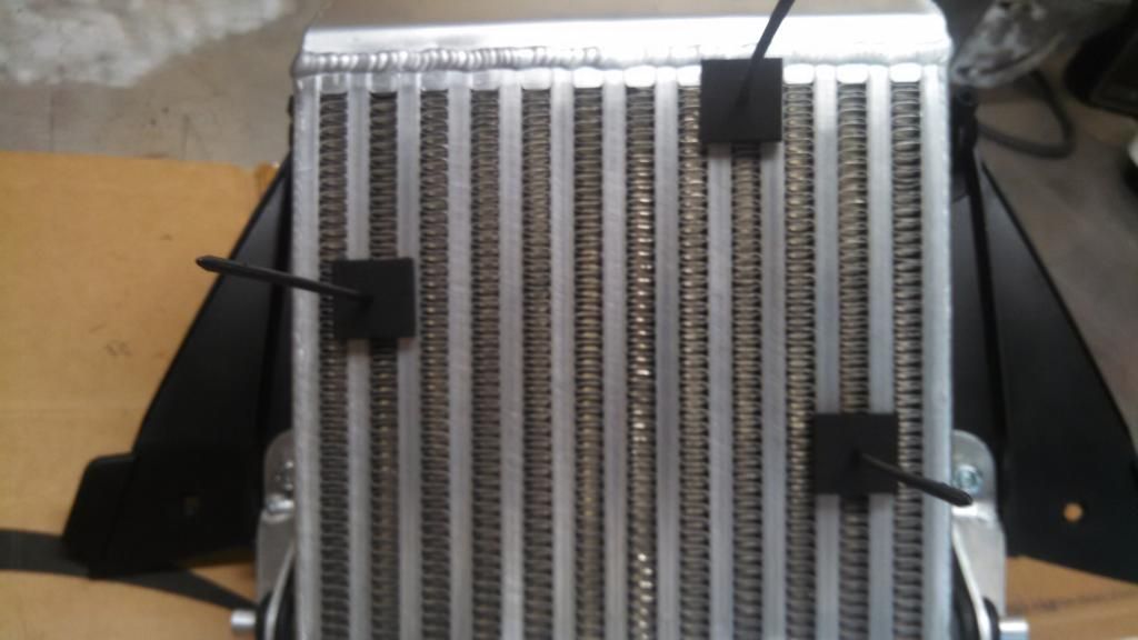
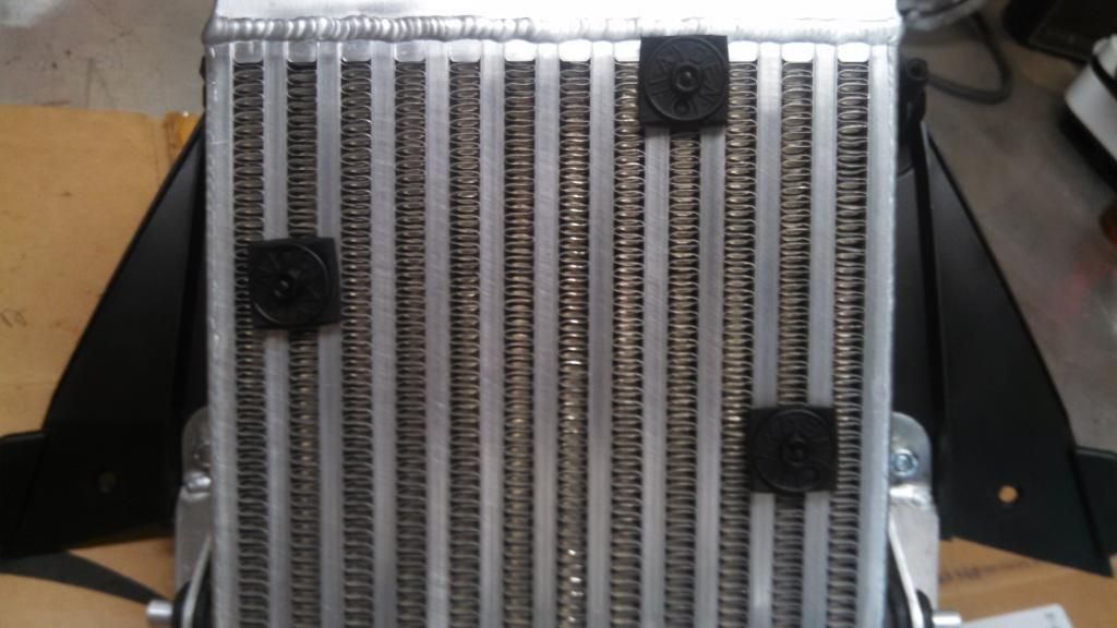
Picture of the fan mounted under the intercooler. You can see the rubber grommet between the intercooler and fan.
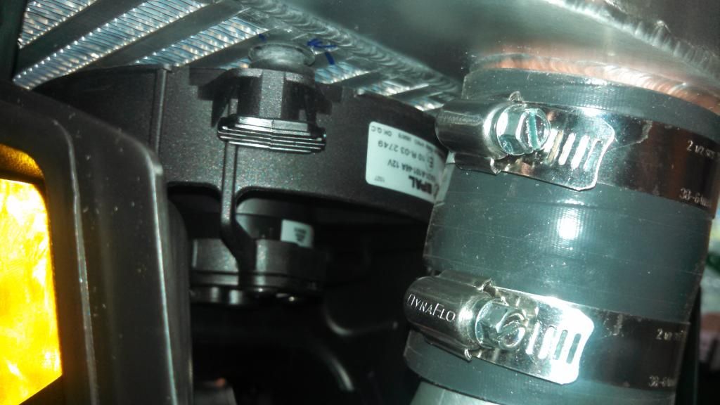

I recommend that you place the plastic nose piece with the intercooler mounted on it on the front of the sled.
This allows you to place the fan under and mark it location to ensure it will not hit anything.
Once this is done, place one of the provided rubber grommets over the plastic piece that secures the fan to the intercooler.
Slide the plastic piece through the intercooler, then place the provided foam piece over and secure in place.


Picture of the fan mounted under the intercooler. You can see the rubber grommet between the intercooler and fan.

Last edited:
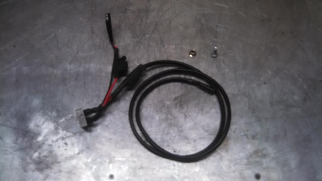
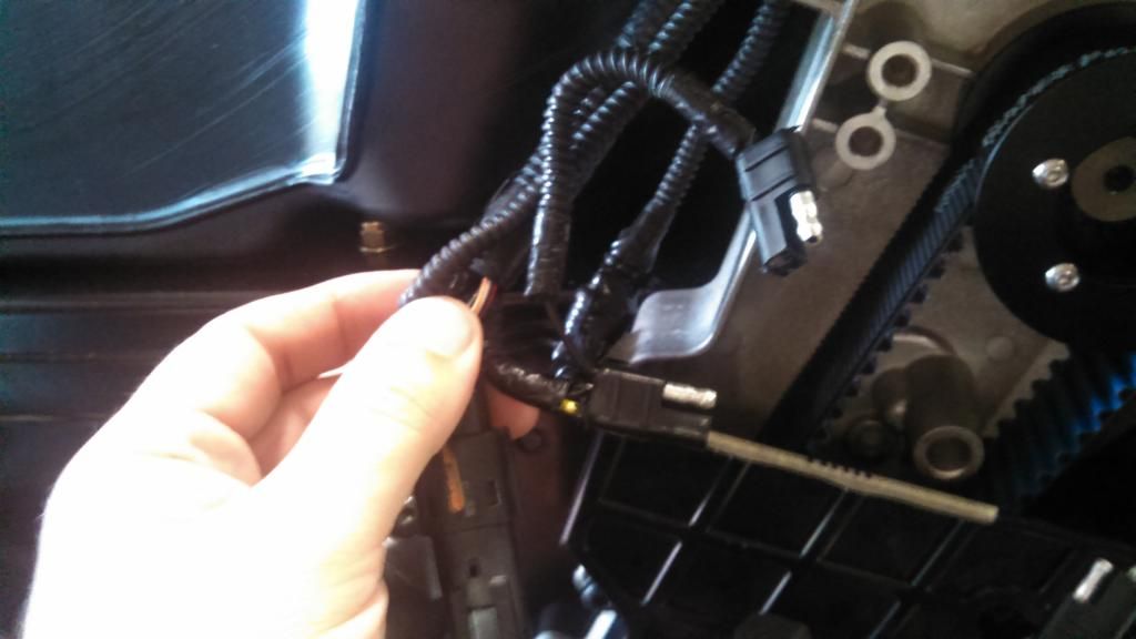
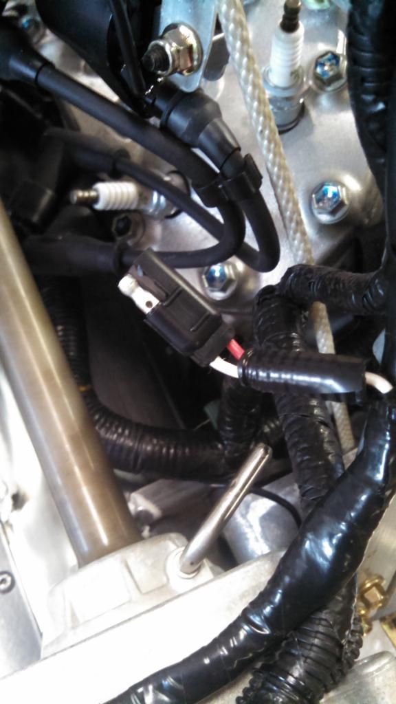
Rectifier and wiring for the fan.
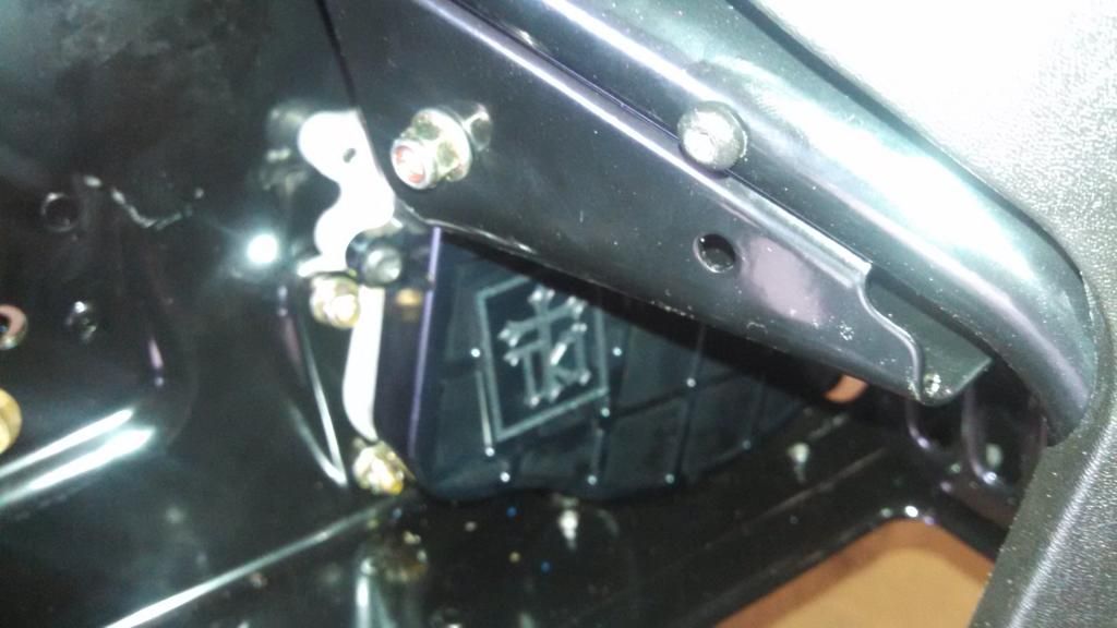
The recommended mounting location is on the MAG side foot well bracket. The rectifier has a threaded hole in it.
After you mount the recoil in its new location you end up with a extra bolt that fits perfectly into the rectifier and
one of the nuts from the stock support brace will thread on to the bolt.
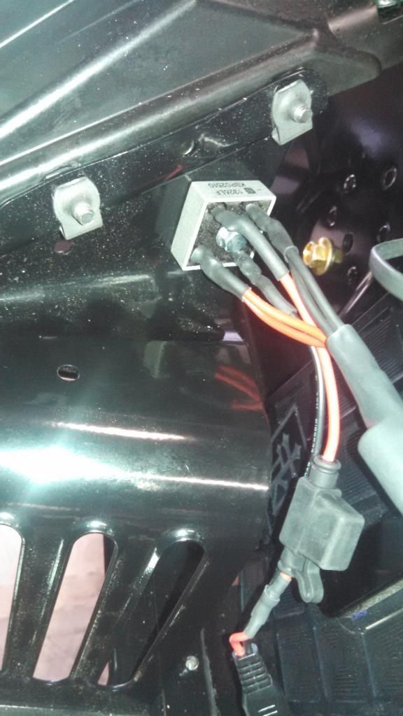
The wiring plugs into the accessory plug next to the chain case.
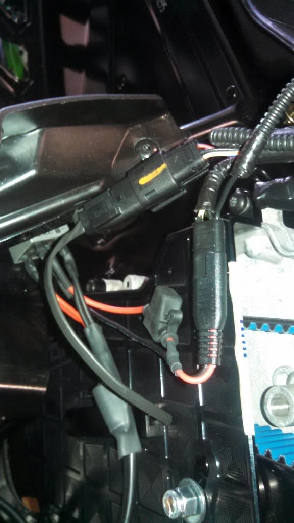
I routed the wiring over the top of the chain case, up the rear vertical support bar and down the support bar with the fuel line on it.

The recommended mounting location is on the MAG side foot well bracket. The rectifier has a threaded hole in it.
After you mount the recoil in its new location you end up with a extra bolt that fits perfectly into the rectifier and
one of the nuts from the stock support brace will thread on to the bolt.


The wiring plugs into the accessory plug next to the chain case.


I routed the wiring over the top of the chain case, up the rear vertical support bar and down the support bar with the fuel line on it.
Last edited:
The front nose piece with the intercooler will be mounted to the front of the sled and not come off with the
hood as it does in the stock configuration. On the lower part of the plastic nose piece there are two small
indents in the plastic that line up with predrilled holes in the front of the sled. Drill out the indents and secure
with two (2) Torx bit head screws.
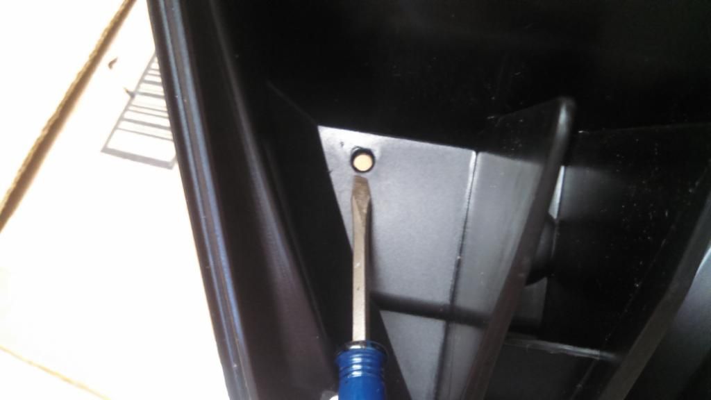
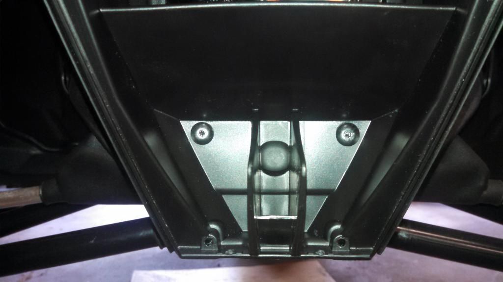
hood as it does in the stock configuration. On the lower part of the plastic nose piece there are two small
indents in the plastic that line up with predrilled holes in the front of the sled. Drill out the indents and secure
with two (2) Torx bit head screws.


Last edited:
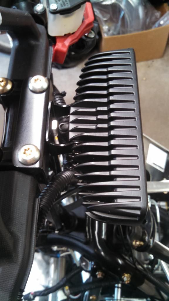
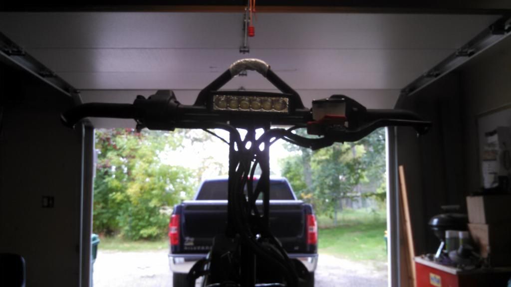
I picked up a LED light from BDX and decided to mount it to the handle bars.
I was told by BDX that the light required 12VDC and is rated at 2A. I spliced in
a two (2) pole plug off the wiring harness from the intercooler fan rectifier, which
is rated to handle 10A. 5A for the fan and 2A for the LED light puts me a 70% of the rectifier output.
I made a mounting bracket that attaches to the front handle bar bolts.
I also spliced a two (2) pole plug on the end of the LED light.
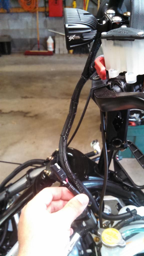
I then built a crossover harness with two (2) pole plugs to follow the stock wiring harness from one side to the other and tie wrapped in place.
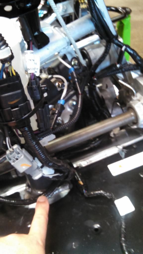
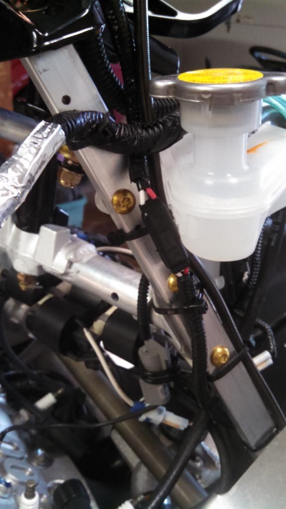
I was told by BDX that the light required 12VDC and is rated at 2A. I spliced in
a two (2) pole plug off the wiring harness from the intercooler fan rectifier, which
is rated to handle 10A. 5A for the fan and 2A for the LED light puts me a 70% of the rectifier output.

I made a mounting bracket that attaches to the front handle bar bolts.

I also spliced a two (2) pole plug on the end of the LED light.

I then built a crossover harness with two (2) pole plugs to follow the stock wiring harness from one side to the other and tie wrapped in place.


Last edited:
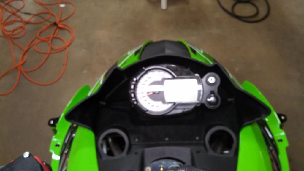
For the headlight delete I went with just the gauge bracket from Reaper Motor Sports
since I already had a partial 4x8 sheet of the plastic material that matched the hood and wanted to use that for the block off plate.
Here's a picture from my mock up.
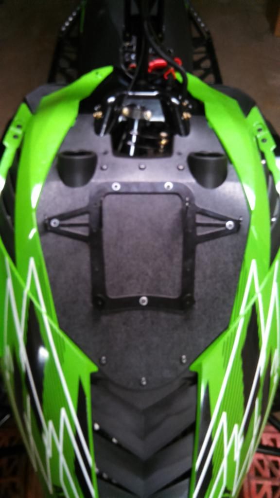
Final block off plate picture. The oval hole on the left is to run the gauge, 12V, key and air temp sensor wiring through.
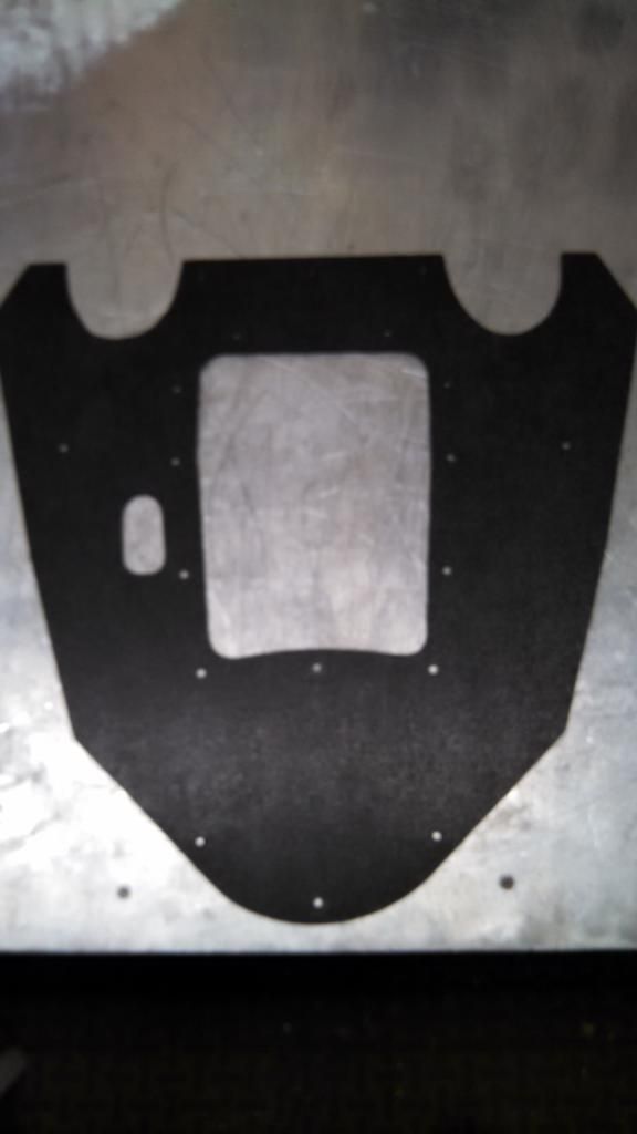
With pet screen installed.
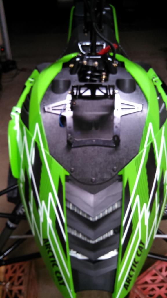
Everything installed on the bracket and connected.
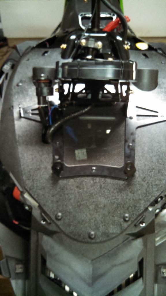
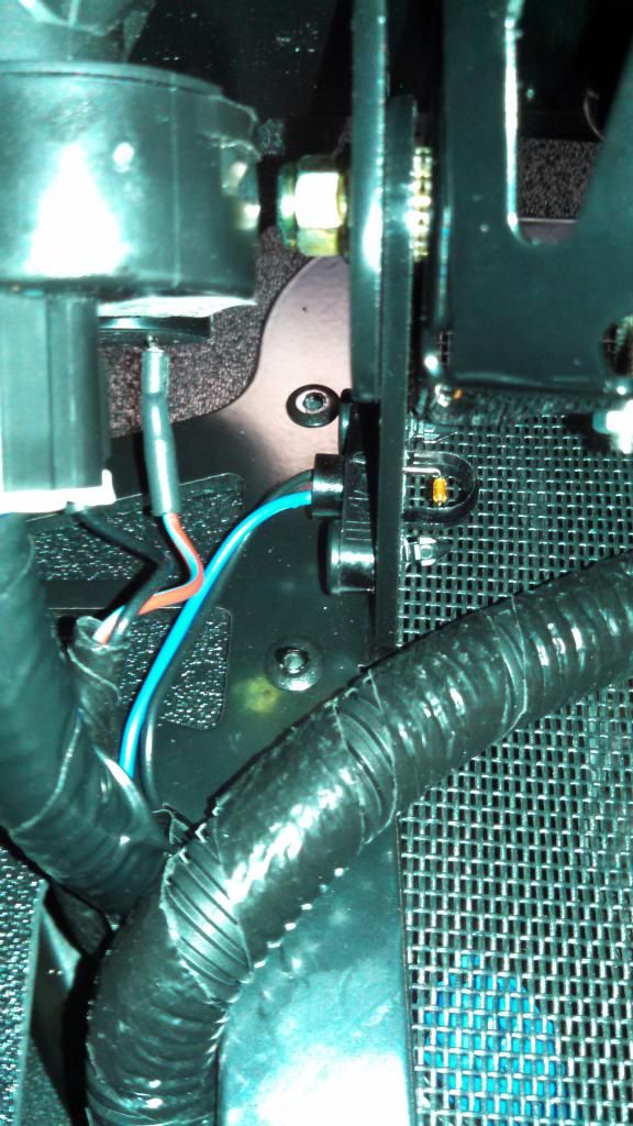
I made a template of the air temp sensor mounting holes from the hood and transferred it over to the gauge bracket. I'll have to see if heat from the hood causes a issue with the sensor mounted over the vent. If so, I'll just turn the sensor around.
Here's the hole that I cut in the hood to run the wiring through. I tried to make it small enough so the hood wiring harness could sit in the depression and not possibly melt from the heat of the exhaust, but large enough to unplug the harness.
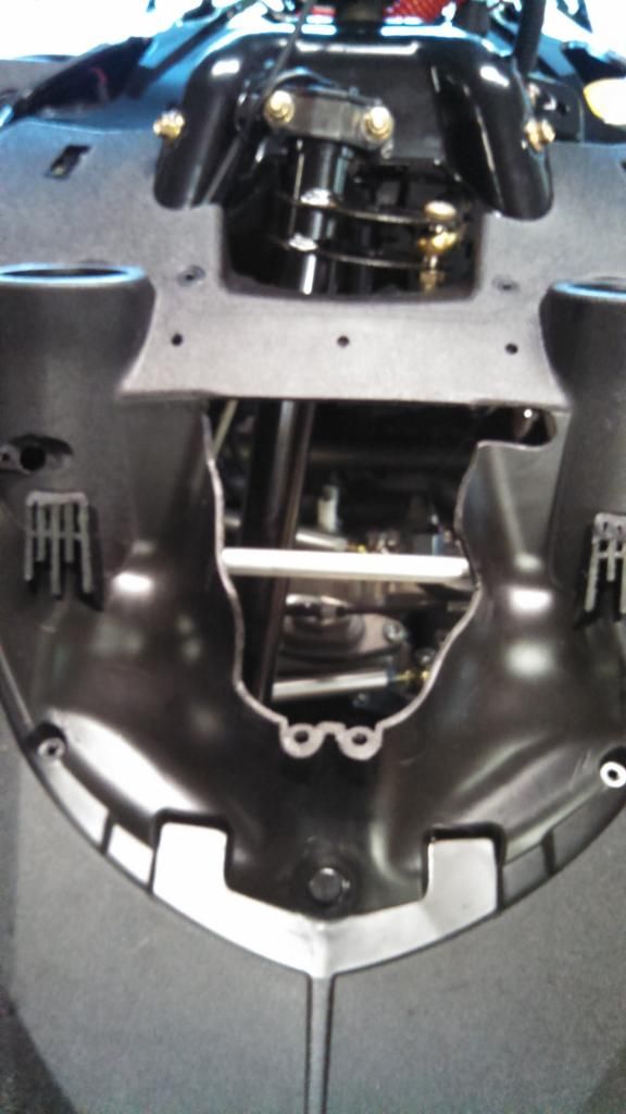
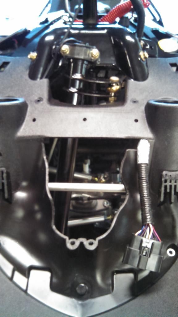
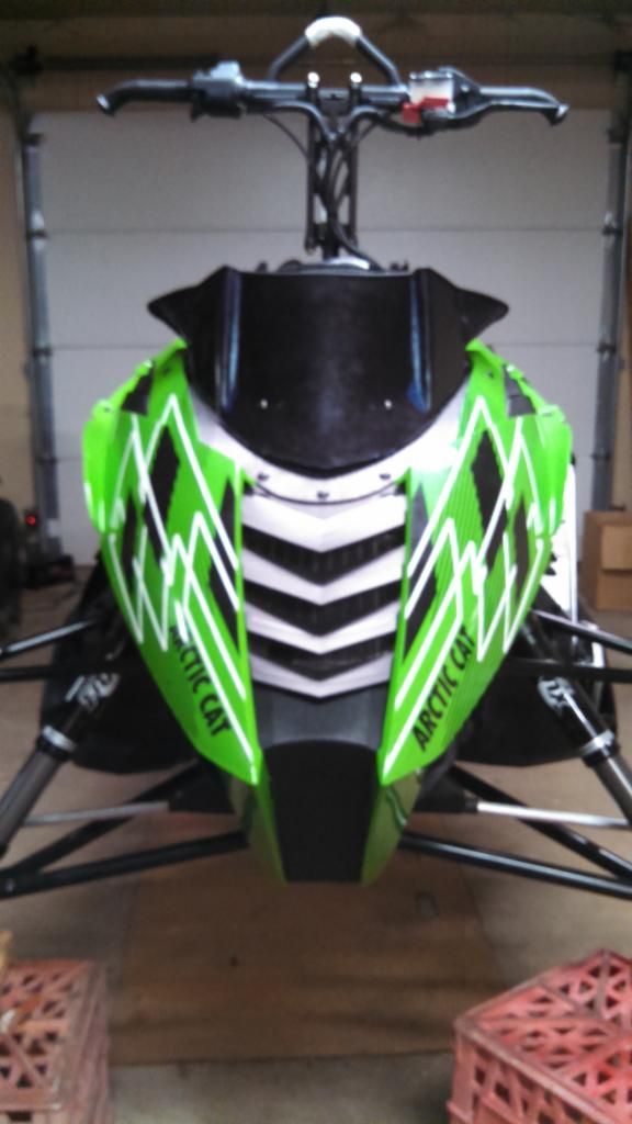
Windshield mounted. I still need to put a screw in the nose to the windshield to keep it down. Doesn't sit flat
due to the curvature of the hood.
since I already had a partial 4x8 sheet of the plastic material that matched the hood and wanted to use that for the block off plate.
Here's a picture from my mock up.

Final block off plate picture. The oval hole on the left is to run the gauge, 12V, key and air temp sensor wiring through.

With pet screen installed.

Everything installed on the bracket and connected.

I made a template of the air temp sensor mounting holes from the hood and transferred it over to the gauge bracket. I'll have to see if heat from the hood causes a issue with the sensor mounted over the vent. If so, I'll just turn the sensor around.

Here's the hole that I cut in the hood to run the wiring through. I tried to make it small enough so the hood wiring harness could sit in the depression and not possibly melt from the heat of the exhaust, but large enough to unplug the harness.


Windshield mounted. I still need to put a screw in the nose to the windshield to keep it down. Doesn't sit flat
due to the curvature of the hood.


Last edited:
wow tundra....Premo quality...very nice build !!
Thanks HC! Still have a lot of little things that I need to do. Somehow those always take the most amount of time. Keeps me busy while I'm waiting for the last few parts to arrive.
This is one cool *** build. Cant wait to see it in action this season. Nice work buddy!
Thanks bro! Gonna have to try and make it to your neck of the woods this year.This is one cool *** build. Cant wait to see it in action this season. Nice work buddy!
Sounds like a plan. Let me know the date & location, Ill be there (with a rental) LMAO!!Thanks bro! Gonna have to try and make it to your neck of the woods this year.
Update
Waiting on parts has pretty much brought things to a standstill on my build. I did pick up pick up a bumper and installed it last week. Finally picked up my POD 300, which is one of the items I was waiting for. I'll try to get that installed this weekend and finish up some additional wiring for my AFR sensor. New skis are on the way as well, should be here midweek next week. I finally decided on Mo-Flow vents so I need to get those ordered and on the way.
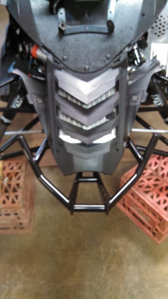
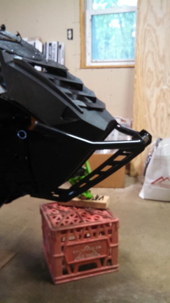
Waiting on parts has pretty much brought things to a standstill on my build. I did pick up pick up a bumper and installed it last week. Finally picked up my POD 300, which is one of the items I was waiting for. I'll try to get that installed this weekend and finish up some additional wiring for my AFR sensor. New skis are on the way as well, should be here midweek next week. I finally decided on Mo-Flow vents so I need to get those ordered and on the way.


Sweet clean build..... sadly my work is keeping me out of town so I had to farm out my SC install....
You will like the bumper, I went tree farming quite a few times with mine last year and only after one massive hit did it bend enough to require replacement.... I think it will protect those fancy schmancy components quite well!
You will like the bumper, I went tree farming quite a few times with mine last year and only after one massive hit did it bend enough to require replacement.... I think it will protect those fancy schmancy components quite well!
This is pretty awesome. I dig it.
I've been down the Forced Induction rabbit hole before... with a Mustang. I can't bring myself to do it with a sled. Once you get a taste of a little boost, you just want more.
Looks like you're doing good work, man. Good luck.
I've been down the Forced Induction rabbit hole before... with a Mustang. I can't bring myself to do it with a sled. Once you get a taste of a little boost, you just want more.
Looks like you're doing good work, man. Good luck.
Thanks guys. It's been a fun build. Just glad winters not here yet. Hope to have it running in a week or two, depending on when the rest of my parts show up.
Similar threads
T
- Replies
- 1
- Views
- 149
T
- Replies
- 59
- Views
- 8K
B


